How to Make a Force Gauge for an Arbor Press
By Ned Gorski
Why Make a Force Gauge for Your Arbor Press?
This project will show you how to take a couple commonly available devices, and create a homemade force gauge, for about half the price of what you can buy one for. Plus it's fun to make some of our own tools.
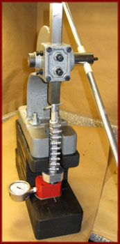
The Force Gauge We'll be Making, Being Used with a Modified Arbor Press
There are two main reasons for using a force gauge on any kind of press when we are making fireworks:
- So that the firework will actually work properly.
- Consistency. So that we can make the same kind of firework, and have it function consistently every time.
What Does "Force Gauge" Mean?
Often, in the specifications for making a particular device such as a whistle or strobe rocket, you'll hear something like, "Press the fuel increments to 7500 PSI (pounds per square inch) on the composition."What does that mean? How do we achieve it, and know we've accomplished it?
Well, first, you need to know that it is not as easy as simply placing your force in the press, pressing down on it, and reading the pounds per square inch. Nope. I wish it were that simple, but it's not. There are other variables you need to take into account.
I'll explain.
The tooling we use to press such devices has a particular area on its end. Let's say we are using a solid 1/2-inch rammer. The diameter of the end of the rammer is 1/2 inch. Its radius is half the diameter, or 1/4 inch. The area of that end is Pi (3.1416) times the radius squared, 3.1416 x 0.25 x 0.25, which is equal to 0.196 square inches. For our purposes, we can round that area off to 0.2 square inches.
For comparison purposes, a 3/4-inch diameter rammer has an end area of 0.44 square inches, slightly more than twice as much area as the 1/2-inch diameter rammer.
If we apply one pound of weight (force) to the top end of our 1/2-inch rammer, that one pound will be applied to 0.2 square inches of area. 1 pound, over 0.2 square inches, or 1 / 0.2, equals 5 pounds per square inch of pressure.
The reverse of that would be done this way. We want, let's say 5 PSI on the composition we are pressing with a 1/2-inch rammer. 5 PSI = X / 0.2 square inches. Multiply both sides by 0.2, and we get 0.2 x 5 = X. X equals 1 pound. We need to apply one pound of force to the 1/2-inch rammer to develop 5 PSI of pressure on the composition.
Force is the number of pounds of weight we apply to some tooling. Pressure is the number of pounds per square inch that is then applied by the tooling to a composition.
Force (pounds) applied to an area (square inches) equals pounds-per-square-inch, Pressure.
If our device specs ask us to apply 7500 pounds per square inch on the composition that will be pressed by our rammer, then we need to know how many pounds of force to apply. Let's say we are using 1/2-inch tooling. 7500 PSI = X pounds of force / 0.2 square inches of area. Multiply both sides by the 0.2, to get 0.2 x 7500 = X pounds of force, so X = 1500 pounds of force. We need to apply that 1500 pounds of force to our 1/2-inch tooling to generate our desired 7500 PSI of pressure on our composition.
Note: All of this may sound a little bit like Greek to you right now. But, as with any other skill, applying it a few times will make it feel a lot more understandable and familiar. It takes practice to make it all feel like second nature.
So, if we want to generate 7500 PSI of pressure with our 1/2-inch tooling, we need to apply 1500 pounds of force to that tooling. That would be the same as piling 1500 one-pound packages of hamburger on top of our tooling.
Note: We've been discussing solid rammers in these examples. Many rammers are hollow to allow fuel to be pressed around a spindle. Typically, on average, the area of the end of a hollow rammer is approximately 3/4 of the area of the end of a solid rammer. So, only 3/4 (0.75) of the amount of force is applied to these hollow rammers, as would be applied to solid ones, to achieve the desired pressure. If 1500 pounds of force is applied to a solid 1/2-inch rammer to develop 7500 PSI on a composition, 0.75 x 1500 = 1125 pounds of force to be applied to a hollow rammer to develop that same amount of pressure.
The bottom line is that, once we've mastered these few calculations, we need to know how much force we are applying to our tooling with our press, and that we've applied the amount of desired force.
How can we know when we've accomplished that? Many fireworkers have Force Gauges in their shops. These gauges can be placed under tooling as a press is applying pressure to it, and the gauge will directly read out how many pounds of force are being applied by the press.
A Force Gauge, Under Rocket Tooling, as a Motor is Being Pressed
Some commercial manufacturers of pyrotechnic tooling make and sell these force gauges for the pyro community. They typically sell for a little more than $100, and are a good addition to a pyro's toolbox, for anyone pressing various devices.
A unique feature to the commercial force gauges is that their cylinders measure one square inch in area. This results in their gauges reading the force directly on their gauge dial. If 1000 pounds is put on one of these units, that 1000 pounds of force is applied to the one-square-inch-area cylinder. 1000 pounds-per-square-inch pressure will then be created in the hydraulic oil inside the unit, and 1000 PSI will read on the gauge's face.

Commercial Force Gauges, with 3,000-PSI and 10,000-PSI Gauges
Force gauges have cylinder sizes, and/or gauge dials, which are calibrated to directly read out the number of pounds of force which are being applied to them. You put the 1500 pounds of hamburger on one of these units, the gauge will read out 1500 pounds, sort of like your bathroom scale.
We will do the same thing with our homemade force gauge once it is assembled: calibrate the gauge dial to directly read out the amount of force which is being applied to it.
Our Homemade Force Gauge
There are two main components which we'll put together to create a force gauge: a short-body hydraulic ram, and a hydraulic pressure gauge.The short-body hydraulic ram is similar to a hydraulic bottle jack except the ram only has a cylinder travel of about a half inch. They are typically used for moving heavy machinery a short distance.
This is the 10-ton short-body hydraulic ram we'll be using:
http://www.harborfreight.com/catalogsearch/result?category=&q=10+ton+short+body+ram

10 Ton Hydraulic Short Body Ram from Harbor Freight
Item #95979
And we'll be using a 2000 PSI hydraulic gauge, like this one from McMaster Carr, part #4053K892, which costs $22.55 at the time of this writing:
http://www.mcmaster.com/#4053k892/=a4skff
The gauge is glycerin filled, rated for up to 2000 PSI, has a 1/4-inch NPT-male bottom-fitting which will screw into the hydraulic ram, and has a stainless-steel case.
Note: Before ordering your gauge, read this whole tutorial, and pay attention to the notes near the end which detail how to choose a pressure gauge with the correct maximum pressure rating to serve your needs.
We'll also need some Teflon tape, and some hydraulic-jack oil, both of which are available at auto-parts stores.
So, for a total of about $60, we have all we need to create our force gauge.

Hydraulic Pressure Gauge, and 10-Ton Short-Body Ram
The ram comes with a hydraulic fitting screwed into its side, which we will not be using. This fitting has a 17-mm hex end on it.
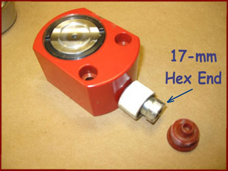
17-mm Hex End on Ram's Hydraulic Fitting
The first thing we want to do is remove that fitting from the ram. The ram needs to be secured by a stout pair of pliers, or a vice, with a rag or other padding to protect it. A 17-mm socket wrench is used on the hydraulic fitting to loosen and remove it.
Note: With the ram I purchased, the hydraulic fitting was very securely installed. I had to apply a large amount of force to the socket wrench, securely holding the ram as I did so, in order to break the fitting loose. This might be a good place to use a strong helper if you have one around.

Loosening and Removing the Hydraulic Fitting from the Ram

Fitting Removed from Ram
Make sure there is no debris in the hole in the ram, from which the fitting was removed. We don't want foreign matter getting into the hydraulic oil and clogging the ports through which the oil travels.
You can see the small hole at the bottom of the threaded hole in the side of the ram. If the ram was being used as intended, hydraulic oil would be pumped through the original fitting, in through that small hole, and into the cavity below the piston of the ram. That pressurized oil would then extend the ram's piston.
We'll be using the ram in exactly the opposite direction, with force applied to the ram's piston by tooling that we are pressing. The piston will then pressurize the oil under it, which will exert pressure through the small hole and into the hydraulic gauge we are about to install into the side of the ram.
First, though, we must extend the ram's piston so that it has some room to travel when a force is applied to it.
Using a coarse threaded screw and a pair of pliers, insert the screw into the hole in the center of the ram's piston, cock the screw sideways, and wiggle the piston until it gradually slides out of the ram about 1/2 inch.
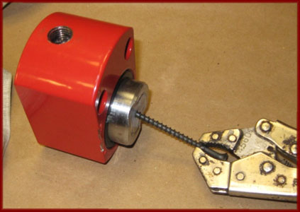
Sliding the Piston out of the Ram's Body
As the piston is slid out of the ram's body, air will be sucked into the cylinder under the piston, through the threaded hole in the ram's side. If the fitting hadn't been removed, air wouldn't be able to enter the ram there, and the piston would not be able to be extended.
The cylinder below the piston is now full of air. We want that area to be full of hydraulic oil instead, though. Grab the piston gently with a pair of pliers, and move the piston slightly in and out of the ram, as you add hydraulic oil to and through the threaded hole in the ram.
Each inward motion of the piston will expel a little air from the cylinder. Add some oil to the hole, and pull the piston outward slightly, sucking the oil into the cylinder. Repeat this until no more air is expelled from the cylinder, and the threaded hole remains full of oil.

Bleeding Air Out of the Ram's Cylinder, as Oil is Added

Topping-Off the Oil in the Ram's Threaded Hole
It is important that all the air has been bled out of the ram's cylinder, and that it has been filled with hydraulic oil, with the piston extended about 1/2 inch.
Wrap the threads on the hydraulic gauge with 4-5 turns of teflon tape. Looking at the end of the threaded base, the tape should be wrapped onto the threads in a clockwise direction, which will tighten the wraps as the threaded fitting is screwed into the ram's body.
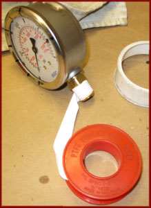
Wrapping the Gauge's Connection Fitting with Teflon Tape
Make sure the tape does not wrap down onto the base of the fitting. Once again, we don't want tape debris getting into the hydraulic oil inside the ram.

Completed Teflon Tape Wraps, Not Going Down Onto the Fitting's Inside End
Now, screw the gauge into the ram, tightening the connection by holding the ram with the padded pliers, once again, and the gauge's base with a wrench. Tighten the gauge until the connection is good and tight and leakproof, and the face of the gauge faces upwards when the ram is on a flat surface.

Tightening the Gauge into the Ram

Hydraulic Gauge and Ram Body Correctly Oriented
The force gauge unit is now ready to use. If all the air was bled correctly out of the ram's cylinder, any weight applied to the ram's piston should create a pressure in the hydraulic oil, which will result in a pressure reading on the gauge. Since oil is barely compressible, the piston will not move noticeably no matter how much pressure is applied to it.
If there is air in the system, though, the piston will move down under a force, and the gauge will have to be removed in order to bleed the rest of the air out of the ram. New teflon tape would have to be used in that case, ensuring that no old tape gets into the ram's oil.
There should never be enough force applied to the unit to move the gauge's needle past its maximum reading, which is 2000 PSI on the original gauge dial.=
Calibrating the Gauge Dial
There is one final modification which we can make to this unit to make it nice and functional. As it stands, the gauge will not directly read out the amount of force applied to the ram, yet.I mentioned earlier that the commercial force gauges have machined pistons and cylinders which have an area of one square inch. So, the amount of force applied to them equates to the same amount of pounds-per-square-inch pressure shown on the gauge. One pound of force on the unit is pressing on one square inch of piston surface area, and will read out on the gauge as one PSI of pressure. Because of the piston's one-square-inch area, we know that 1 PSI gauge reading equates to one pound of force on the unit.
But our short-body ram's piston does not have a one-square-inch area. The piston and cylinder of the ram have a diameter of 1.7 inches. They therefore have an area of 2.27 square inches.
One pound of force applied to our ram will be applied to the 2.27 square inch area of the piston, and will result in a pressure of 1 / 2.27 pounds-per-square-inch, or 0.44 PSI on the gauge.
500 pounds of force on the 2.27 square-inch-area piston will result in 500 / 2.27, or 220 PSI on the gauge.
Likewise, 1000 pounds of force will read out 440 PSI, 1500 pounds of force 660 PSI, and 2000 pounds of force will read 880 PSI on the gauge.
You can see in this closeup of the gauge dial, that a hashmark has been created at 220 PSI, to indicate 500 pounds of force. Likewise there is a hashmark with a "1" at 440 PSI to indicate 1000 pounds of force, a mark at 660 to indicate 1500 pounds of force, and a "2" marked at 880 PSI to indicate 2000 pounds of force.
Additional marks indicate 2500, 3000, 3500, 4000, and 4500 pounds of force.

Hash-Marks Indicating Actual Force Being Applied to the Unit
Dividing any goal amount of force we are trying to exert on our tooling by 2.27 will determine what reading on the original gauge dial we are shooting for.
Let's say we want to press a composition in a 1/2-inch device to 7500 PSI on the composition. That 7500 psi is being applied by a rammer with 0.2 square inches of area, so we need to apply 0.2 x 7500 = 1500 pounds of force.
1500 divided by 2.27 equals 660 PSI reading on our force gauge, where that 1500 hash mark is. We simply press until the gauge needle gets to that 1500 hash mark at 660 PSI, and the composition has been pressed with the desired pressure.
Obviously, then, the maximum amount of force that can safely be applied to this force gauge without damaging the gauge, is 4500 pounds of force, which will result in a gauge reading of 1980 PSI, very close to its maximum safe reading.
Different capacity gauges could be purchased to adjust for the maximum force you wish to apply on the unit. If your press is rated for only 1-ton, 2000 pounds of force, then 2000 pounds of force would read 880 PSI on the gauge, and you might wish to get a 1000 PSI gauge instead of the 2000 PSI one used in this project.
Or if you wished to max out the amount of force the ram is capable of, 10 tons, or 20,000 pounds of force, with some super-duper press, then 20,000 divided by 2.27 will result in approximately a 8800 PSI reading on the gauge, so a 10,000 PSI gauge might be what you want to purchase.
Using a gauge with a maximum pressure reading that is close to the maximum you plan on exerting on it, guarantees the greatest amount of gauge readout precision as you are using your force gauge.
One final tip is to mark on your press base where the force gauge should sit to be centered under the press's ram. This makes it easy to locate the force gauge correctly each time it is used.

Base of Press Marked with Optimum Force Gauge Location
Note: I heard about this tip from a guy, who heard about it from a guy, who heard about it…. I couldn't track down the originator of this idea for a homemade force gauge, but it's a fun one which allows us to make one more tool in our pyro arsenal.
Happy Pressing.